Apple Xserve Setup Guide Setup Expansion And Hardware Specifications For The Xserve
About This Guide
This setup guide shows you how to install the Xserve computer in a rack and how to install or replace components inside the Xserve.
This guide describes the 3rd-generation Intel-based Xserve (early 2009):
- For information about unpacking the Xserve and installing it in a rack, see Chapter 1.
- For information about installing or replacing drive modules, memory, PCI cards, power supplies, or the system battery, see Chapter 2.
- For a summary of Xserve specifications, see Appendix A.
- For safety, maintenance, and regulatory information, see Appendix B.
When You Finish Installing the Xserve
For information about starting up the Xserve for the first time, configuring the server software, and using the Xserve, see the Xserve User Guide on the Admin Tools disc that comes with the Xserve.
To learn about the Mac OS X Server software installed on the Xserve, see Mac OS X Server: Getting Started, also on the Admin Tools disc that comes with the Xserve.
If you have an Xserve RAID Card installed in your Xserve, see the RAID Utility User Guide (available at www.apple.com/xserve/resources.html) for information about setting up RAID sets and volumes.
The Xserve Setup Guide, Xserve User Guide, Mac OS X Server: Getting Started, and other server guides are also available at www.apple.com/server/resources.
For More Information
The Apple Service & Support website offers in-depth product information and technical resources, including articles, discussions, and downloadable software updates. Visit the site at www.apple.com/support/xserve.
Installing the Xserve
This chapter shows you how to install the Xserve in an equipment rack.
The information in this chapter will help you gather the tools you’ll need, choose a suitable location for the Xserve, and install it in a rack. When you’ve finished installing the Xserve, you’ll be referred to the Xserve User Guide for information about starting up the Xserve for the first time.
Tools and Parts You’ll Need
- A medium-size (#1) Phillips screwdriver
- The slide rails, rail extensions, and alignment tool that come with the Xserve
- Rails for use with racks of all depths (2)
- Short extensions for racks 24 to 29 inches deep (2)
- Long extensions for racks 29 to 36 inches deep (2)
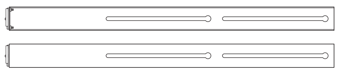
- Alignment guide
- Enclosure key
- Rails for use with racks of all depths (2)
Choosing a Suitable Location
The Xserve is designed for rack mounting. Review the following paragraphs to be sure the location you choose satisfies the Xserve space, electrical, and environmental requirements.
Rack Compatibility
You can install the Xserve in any open or closed (cabinet-style) 19-inch-wide four-post rack from 24 to 36 inches deep using the rails included with the Xserve. The Xserve occupies 1.75 inches (1U) of vertical rack space.
Important: Your rack should satisfy the American National Standards Institute (ANSI)/ Electronic Industries Association (EIA) standard ANSI/EIA-310-D-92, International Electrotechnical Commission (IEC) 297, and Deutsche Industrie Norm (DIN) 41494.
Rack Stability
Make sure the rack is stable and strong enough to support installed equipment.
When working with equipment in the rack, never slide out more than one unit at a time, and keep all other equipment secured in the rack.
WARNING: Don’t put a display or other device on top of the Xserve. The extra weight can damage components inside the Xserve, strain the rack rails, and make the rack unstable. Devices not secured in the rack can fall on you.
Space Requirements
Air to cool the Xserve flows from front to back. Make sure nothing blocks the openingsin the front and back panels of the Xserve. When installed, the Xserve slides in and out of the rack from the front. Make sure you have at least 36 inches (1 meter) clear in front of the Xserve so you can remove it.
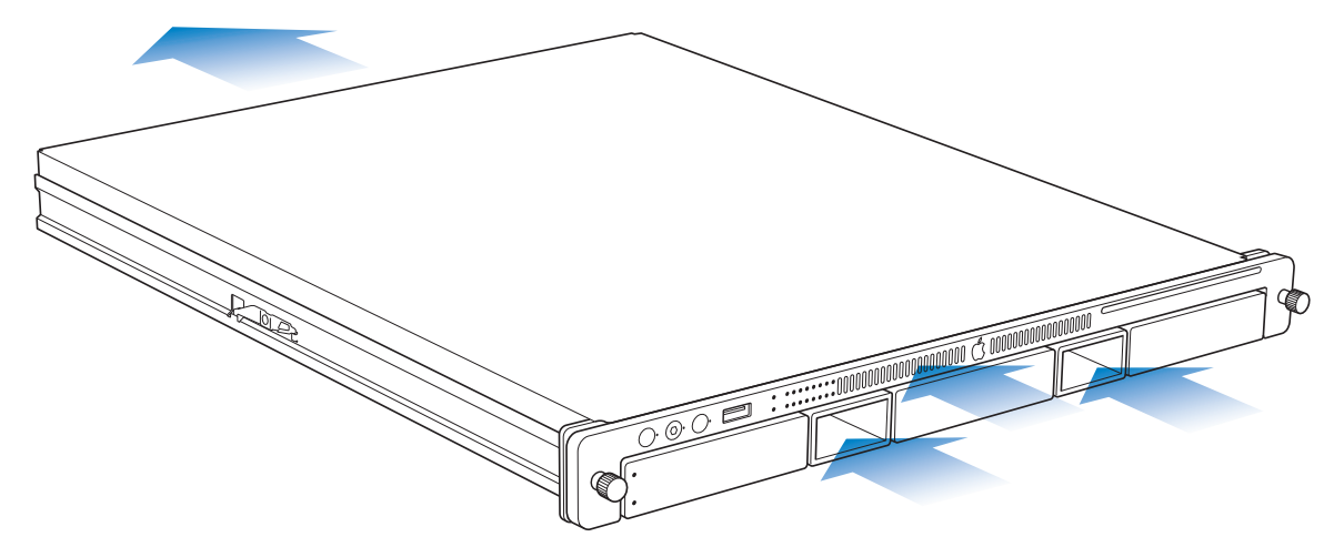
Do not block the air flowing through the Xserve.
Electrical Power Requirements
Be sure that the available circuitry and power connections can support the combined power needs of the Xserve and all other equipment in the rack. For information about the electrical power requirements of the Xserve, see Appendix A,“Specifications,”. Make sure that the power connections for the Xserve and all other equipment are grounded according to local and national standards.
Operating Environment
Make sure that the ambient temperature in the rack is within the limits established for the Xserve and all other equipment. For the Xserve operating temperature requirements, see Appendix A,“Specifications,” . Make sure that both the rack itself and the room where the rack is located are sufficiently ventilated to maintain the necessary temperature range.
Installing the Xserve
Follow these instructions to install the Xserve in an equipment rack.
Installation Summary
- Step 1: Remove the shipping material
- Step 2: Assemble a pair of slide rails that are the right length for your rack
- Step 3: Install the rails loosely in the rack
- Step 4: Align and secure the rails
- Step 5: Slide the Xserve into the rack
- Step 6: Connect the cables
- Step 7: Connect a keyboard, display, and mouse (optional)
Installing Optional Components Before You Begin
To work inside the Xserve, you need to remove it from the rack. If you plan to install additional memory, PCI cards, or other internal components before you start using the Xserve, you might want to do so now. For help installing components, see Chapter 2.
Step 1: Remove the protective shipping materials
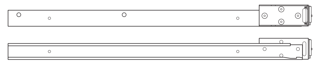
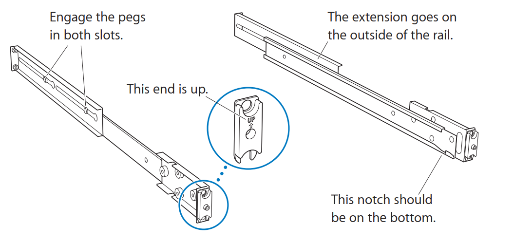
The Xserve comes with both short and long extensions that you combine with standard front rails to create a pair of rails that are the right depth for your rack.
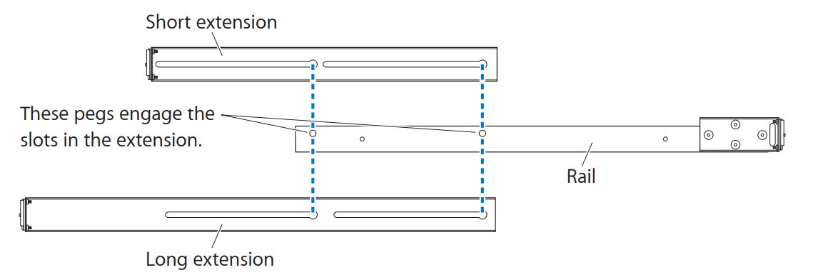
- Slide a matching rear extension onto each of the two front rails.
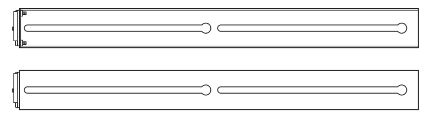
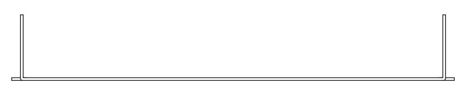
Step 3: Install the rails loosely in the rack
- Place an assembled rail in the rack (it will support itself temporarily while you gather the fasteners). The way you fit the rail depends on the rack.
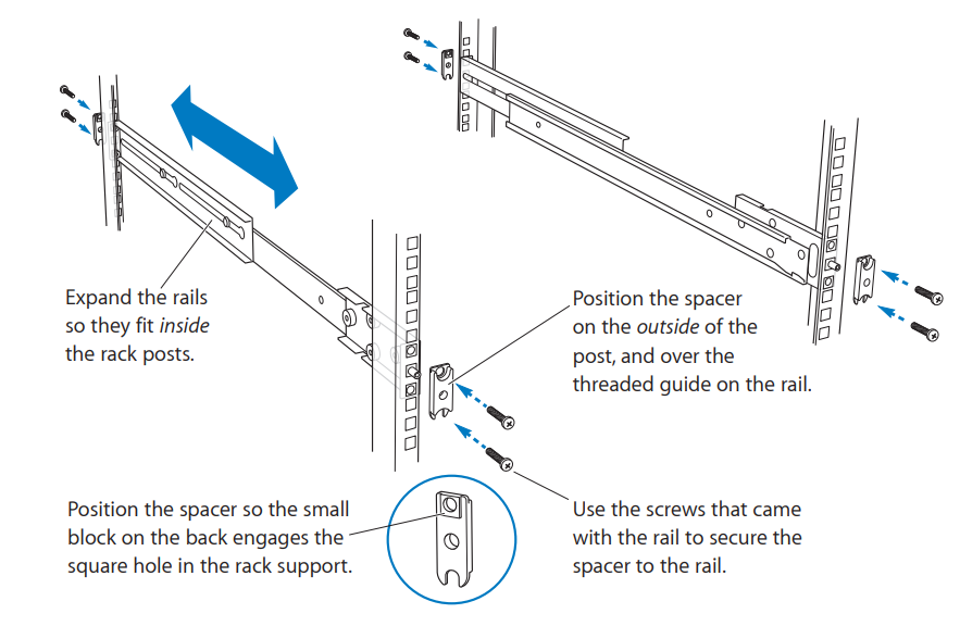
- If you have a square-hole rack, start with the rail flanges inside the posts and expand the rail between the front and rear posts until the small round guide on each flange extends through the rail.
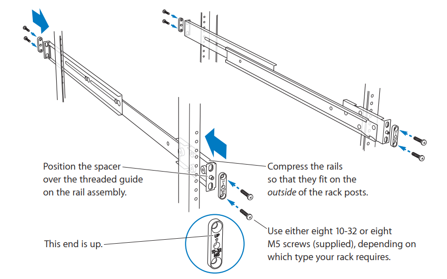
- If you have a threaded-hole rack, start with the rail flanges outside the rack posts and compress the rail into position.
- If you have a square-hole rack, start with the rail flanges inside the posts and expand the rail between the front and rear posts until the small round guide on each flange extends through the rail.
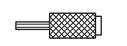
- Slide a spacer, with the arrow up, over the small round guide at the ends of each rail and install the mounting screws finger tight.
Don’t tighten the mounting screws until you align the rails in the next step.
Step 4: Align and secure the rails
To make sure the Xserve slides easily in and out of the rack, use the alignment guide to position the rails in the rack before you tighten the mounting screws.
- Insert the alignment guide in the front of the rails.
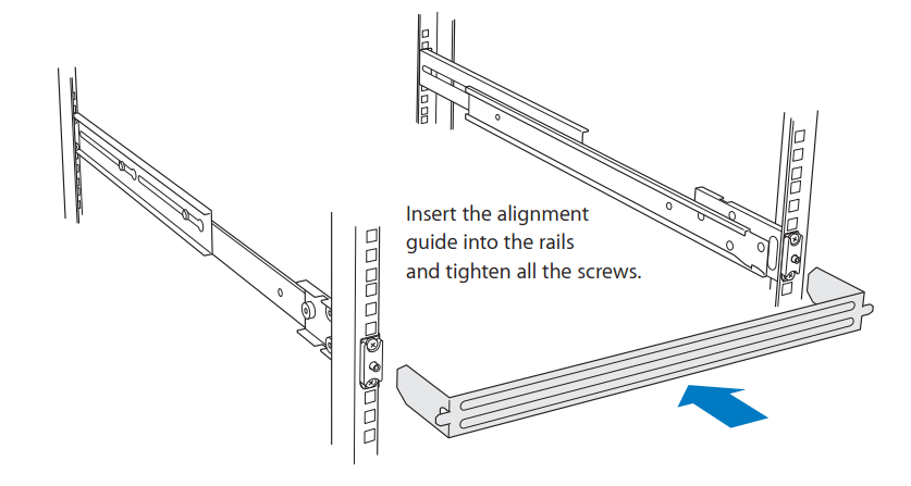
- Tighten the front mounting screws mportant: If you have a square-hole rack, make sure the raised alignment block on the back of each mounting spacer is seated properly in the hole in the rack post as you tighten the screws.
- Tighten the rear mounting screws.
- Remove the alignment guide.
Step 5: Slide the Xserve into the rack
- Guide the slides on the Xserve into the channels on the rails.
Important: Make sure both the left and right slides on the Xserve go inside the rail channels. If you have difficulty, set aside the Xserve and use the alignment guide to check the spacing between the rails.
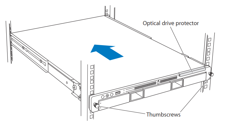
- Slide the Xserve into the rack until it stops.
- Tighten the thumbscrews at each end of the front panel to secure the Xserve in the rack.
- Remove the plastic optical drive protector
Important: Keep the protector and return it to the drive slot whenever you move the Xserve to another location or pack it for shipping.
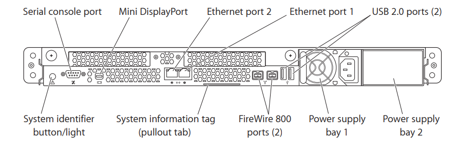
Step 6: Connect the cables
- Connect a power cord to the power supply and secure it with the wire clip.
The fan in the power supply and some system status lights come on when you connect the power cord, before you turn on the Xserve. - Connect the network cables.
If you’re using only one Ethernet cable, connect it to port 1.
Step 7: Connect a keyboard, display, and mouse (optional)
You can connect a display, keyboard, and mouse directly to the Xserve. You can also manage the Xserve without connecting a display or keyboard by using tools such as Server Admin, Server Monitor, Apple Remote Desktop, and the command line.
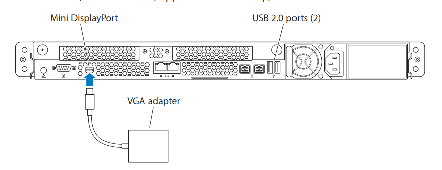
- Connect the keyboard to one of the USB ports on the back panel.
- Connect the mouse to the second USB port or to the keyboard.
- Connect the video cable to the Mini DisplayPort on the back panel. If necessary, use a VGA or DVI adapter, sold separately.
Where to Go from Here
When you finish installing the Xserve, look in the following guides for information about starting up, configuring, and using it.
Starting Up the Xserve
The Xserve User Guide (a PDF file on the Admin Tools disc) includes:
- An overview of Xserve controls and components
- Information about how to start up and shut down the Xserve
- Tips for monitoring the status of the Xserve and the services it hosts
- Instructions for updating or reinstalling the server software
- Solutions to some common problems
Configuring the Server Software
The first time you turn on the Xserve, Server Assistant asks you for basic information that Mac OS X Server needs in order to start up and connect to the network. For help with the setup process, see Mac OS X Server: Getting Started on the Admin Tools disc that comes with the Xserve.
Setting Up RAID Volumes
If your Xserve includes an Xserve RAID Card, see the RAID Utility User Guide (available at www.apple.com/xserve/resources.html) or the RAID Utility onscreen help for information about setting up RAID sets and volumes using the Xserve drive modules.
Installing or Replacing Components
This chapter shows how to install or replace drive modules and internal Xserve components.
You can install or replace these components while the Xserve is in the rack:
- Drive module (page 24)
- Power supply (page 28)
To install or replace these components, you must remove the Xserve from the rack and open it:
- Memory (page 33)
- PCI Express card (page 38)
- Battery (page 43)
For a quick glance inside the Xserve, turn the page.
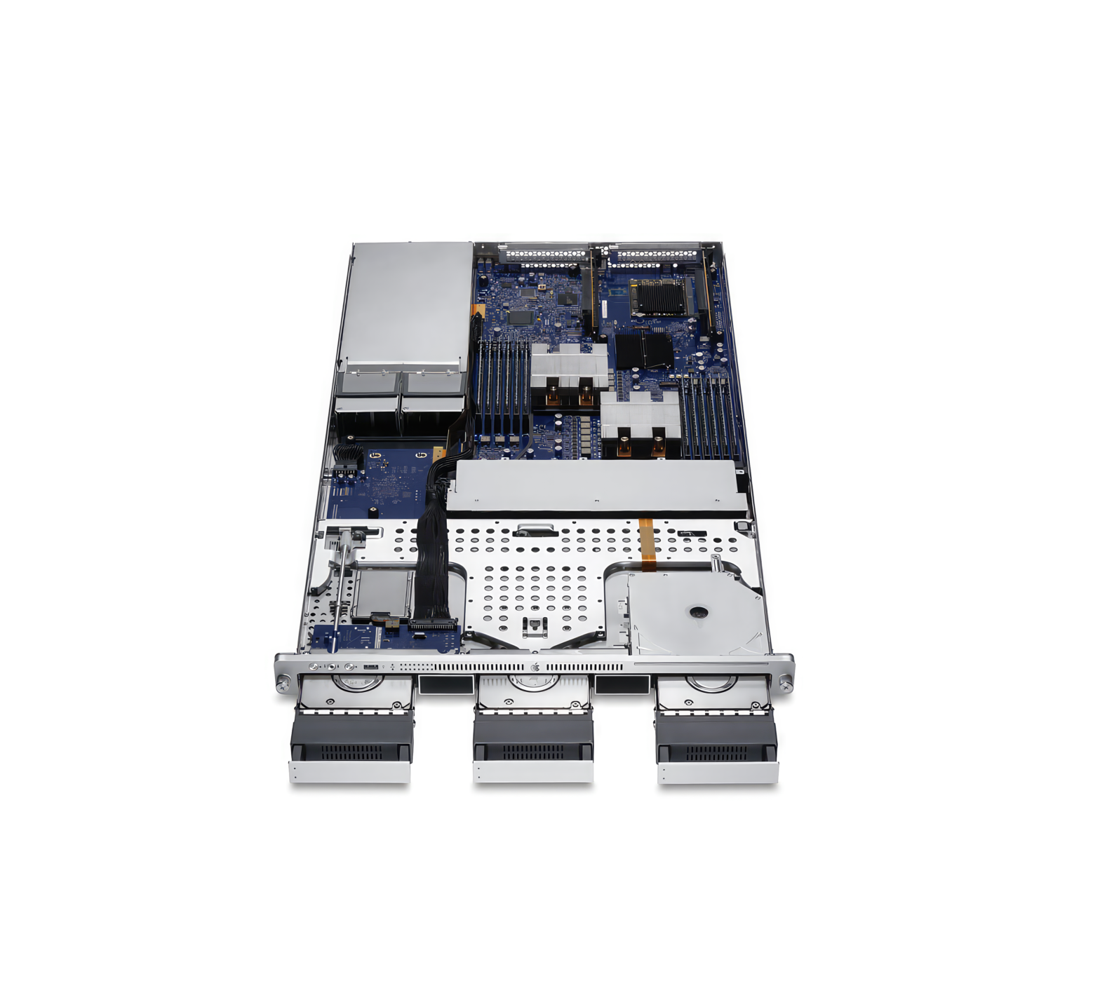
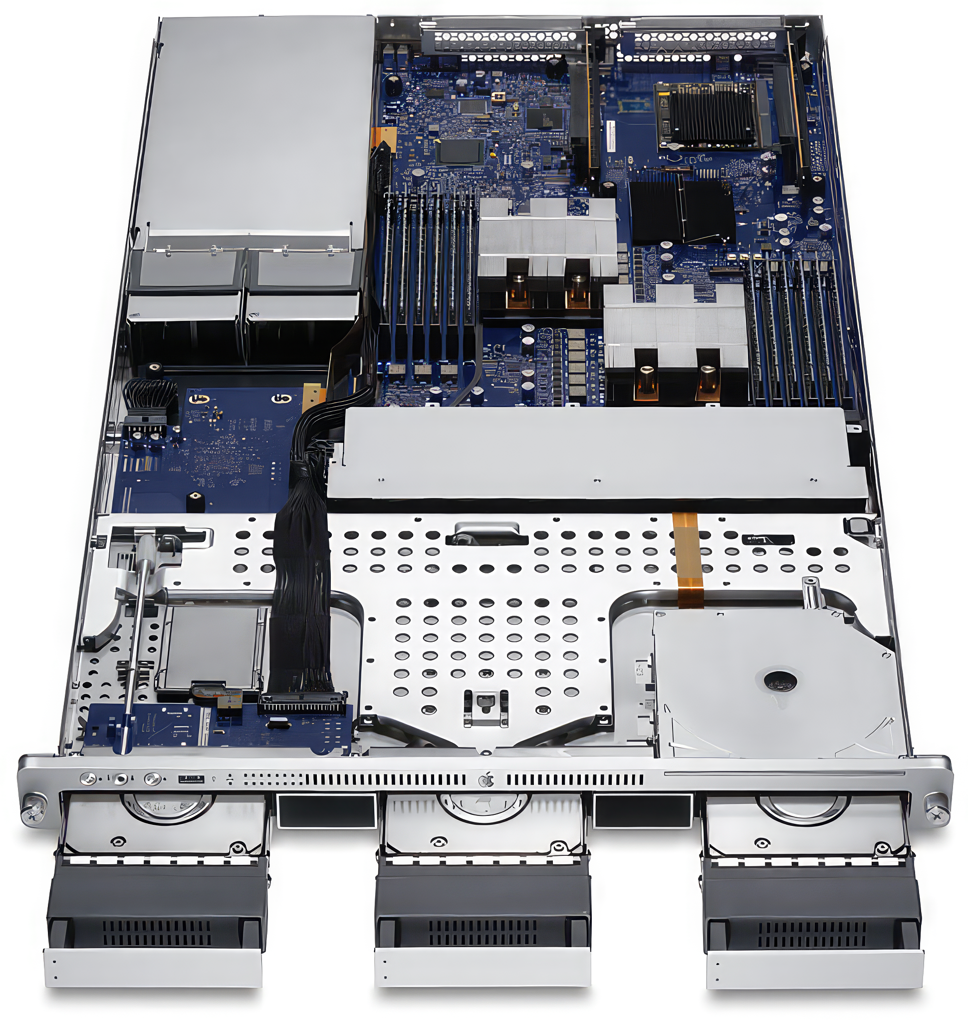
Xserve at a Glance—Internal Components
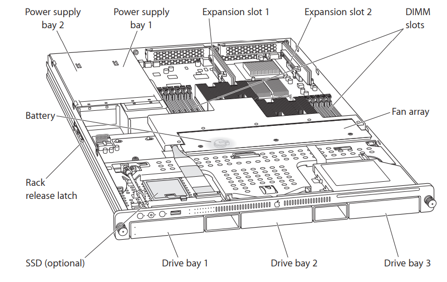
Power supply bays
You can install one or two power supplies in the Xserve. When two supplies are installed, they share the load. If one supply fails, the other takes over the full load. See “Installing or Replacing a Power Supply” .
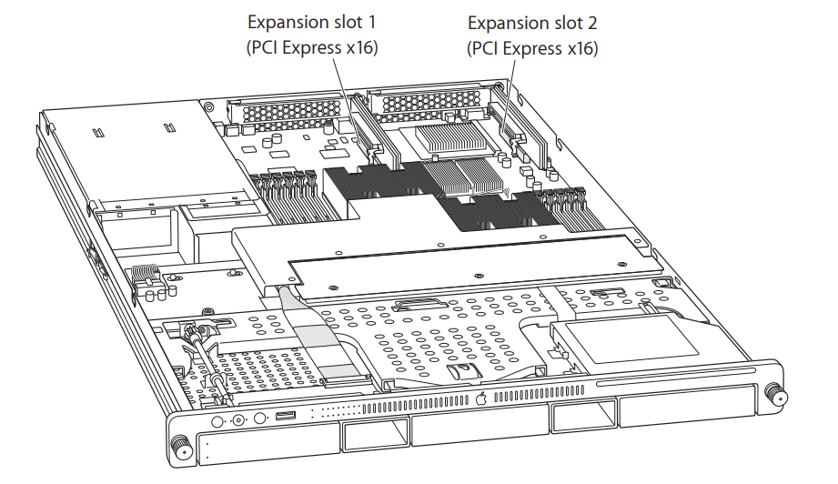
Expansion slots
You can install a half-length (6.6 inch) PCI-E card in slot 1 and a 9 inch PCI-E card in slot 2. See “Installing a PCI Express Card” .
DIMM slots
You can install up to twelve error-correcting dual inline memory modules (DIMMs) in these slots. See “Adding Memory”.
Fan array
The fan array draws cooling air through the Xserve from front to back.
Drive bays
You can install SATA (Serial ATA) Apple Drive Modules or qualified third-party SAS (Serial Attached SCSI) drive modules. See “Installing or Replacing a Drive Module”.
Solid-state drive (SSD)
If you ordered your system with an SSD, the Xserve comes with the SSD set up as the startup disk.
Rack release latch
This latch stops the Xserve about halfway out of the rack. Press to release.
Battery
The battery on the main logic board powers the system clock and preserves basic system settings (in NVRAM) when power supplies are disconnected. See “Replacing the Battery”.
Installing or Replacing a Drive Module
If you’re not using an Xserve RAID Card, the drive modules in the Xserve are hotpluggable, so you can add, remove, or replace them while the Xserve is operating. A status light on the drive handle indicates when it’s safe to remove a drive without risk to the information stored on it.
f you are using an Xserve RAID Card, you can replace a failed drive while the Xserve is operating. However, if you want to replace an entire RAID set, turn off the Xserve before you move the drives.
About Drive Modules for the Xserve
The Xserve accepts both SATA (Serial ATA) Apple Drive Modules and qualified thirdparty SAS (Serial Attached SCSI) drive modules. For information on qualified drive modules, go to www.apple.com/store. If you are using an Xserve RAID Card, be sure to use drive modules that are all the same size and type.
To install or replace a drive module:
- If the Xserve case is locked, use the enclosure key to unlock the security lock on the front panel.
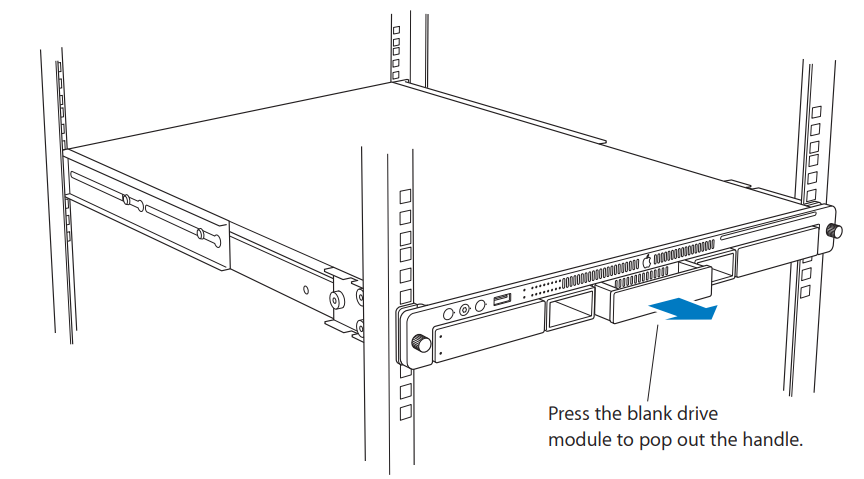
- Remove the blank drive module or the drive module that’s currently installed.
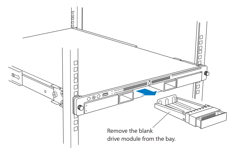
If there is a blank drive module in the bay, press the handle on the front to pop it out. Then pull the module out and put it in a safe place.
Important: Save the blank drive module. Always keep a blank drive module in any unused drive bay to maintain proper airflow through the Xserve.
If there is a drive module already in the bay:
a Make sure the drive currently in the bay is not being used by any application or being shared by the Xserve.
b Press the handle on the drive module so the handle pops out.
c Wait for the green, upper disk status light to go off. Then grasp the handle and pull the drive module out of the bay. If the light doesn’t go out after 20 seconds, an application probably has a file open on the drive. - Pick up the drive module you are installing, press and release its handle to open it, and slide the module into the bay until it is firmly seated.
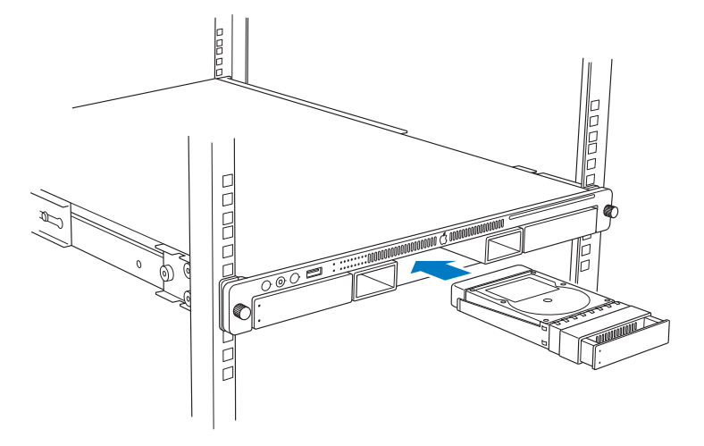
- Press the handle in flush with the front panel.
The disk status light turns green to indicate normal operation.
Installing or Replacing a Power Supply
You can install or replace a power supply from the back panel without removing the Xserve from the rack. If the Xserve has two power supplies, they are hot-swappable; the Xserve continues to operate using only one supply while the second is removed.
Important: Install power supplies with a rating of at least 750 watts. The power supplies from some earlier Xserves are rated at less than 750 watts.
To remove a power supply:
- Unplug the power cord from the power supply you are removing.
- Pull the handle to release the power supply and slide it out of the bay.
WARNING: The power supplies in a running Xserve might be hot.
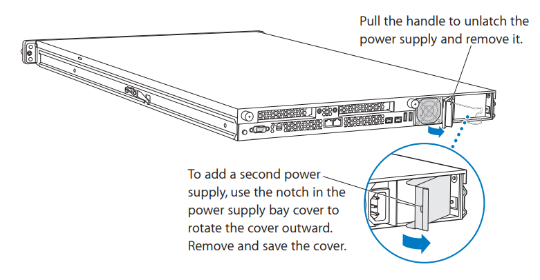
To install a power supply:
- Pull open the handle on the new power supply, press on the wire fan screen (not the handle) to slide the supply all the way into the bay, and then press the handle closed to seat the power supply and lock it in place.
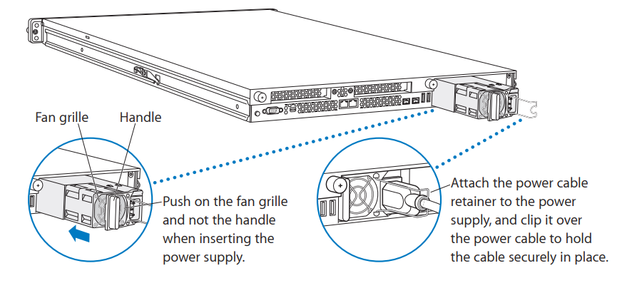
- Connect the power cord to the power supply
f the Xserve is already running on a second power supply, the status light on the new supply turns green to indicate normal operation as it starts sharing the load. If the Xserve isn’t turned on, the supply status light blinks green when the power cord is plugged in to an outlet with power.
Opening and Closing the Xserve
Before you can install or replace memory, PCI cards, or the system battery, you need to shut down the Xserve, remove it from the rack, and open it.
Working Safely Inside the Xserve
Always touch the Xserve chassis to discharge static electricity before you handle any components inside the Xserve. To avoid generating static electricity, do not walk around the room until you have finished installing the expansion card, memory, or other internal component and have replaced the Xserve cover. To minimize the possibility of damage due to static discharge, wear an antistatic wrist strap while you work inside the Xserve.
To open the Xserve:
- Shut down the Xserve (see the Xserve User Guide for help) and then wait a few minutes to let the Xserve internal components cool.
WARNING: Always shut down the Xserve before opening it to avoid damaging its internal components or the components you want to install. Don’t open the Xserve or try to install items inside while it is turned on. Even after you shut down the Xserve, its internal components can be very hot. Let it cool down before you open it. - If the Xserve case is locked, use the enclosure key to unlock the security lock on the front panel.
- Unplug all cables from the Xserve.
If you have trouble releasing a cable from the back panel, try using a small screwdriver or other flat tool to depress the tab on the cable connector. - Loosen the thumbscrews at both ends of the front panel.
- Grasp the thumbscrews and pull the Xserve forward until the safety latches engage (about halfway out of the rack).
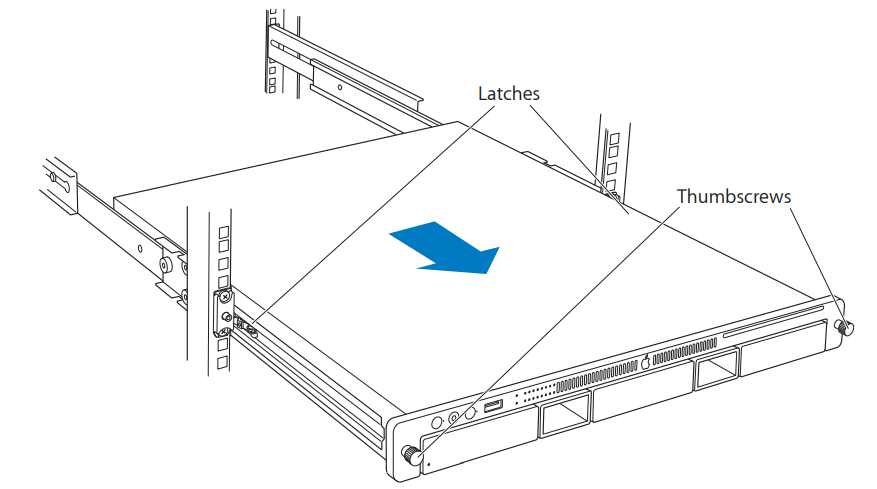
- When the safety latches engage, grip the Xserve where it emerges from the rack, press down on the latch tabs with your thumbs, and slide the Xserve the rest of the way out of the rack rails. Set the Xserve on a flat surface.
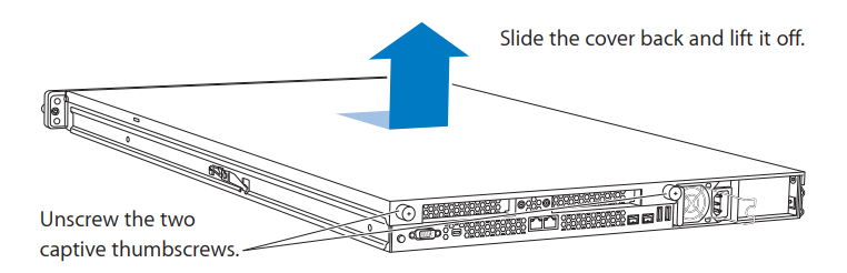
- Loosen the thumbscrews at the back of the top cover and slide the cover back and up to remove it.
If you have difficulty removing the cover, check the enclosure lock on the front panel.
Important: To minimize the possibility of damage to Xserve components due to static discharge, wear an antistatic wrist strap while you work inside the Xserve.
- When you’re finished working inside the Xserve, replace and secure the cover, slide the Xserve back into the rack, and tighten the front thumbscrews to secure the Xserve in the rack. If the server case was locked, use the enclosure key to lock the security lock on the front panel.
Adding Memory
The Xserve has 12 memory slots. The systems come with at least 3 GB of memory on three 1 GB DIMMs. To improve performance and capacity, you can install up to twelve DIMMs.
You can use the following memory in the Xserve:
- 1066 MHz DDR3 ECC (Error Correcting Code) DIMMs
- 1 GB, 2 GB, or 4 GB DIMMs (optimally, 6 or 12 identical DIMMs for a dual-CPU Xserve and 3 or 6 identical DIMMs for a single-CPU Xserve)
Important: Apple recommends that you use Apple-approved DIMMs. Other DIMMs might degrade the performance of the Xserve. DIMMs from older Xserve systems are not compatible with this Xserve. You can purchase Apple-approved memory online from the Apple Store at www.apple.com/store.
Before you purchase DIMMs other than those recommended by Apple, make sure that the memory manufacturer conforms to the Joint Electron Device Engineering Council (JEDEC) specification. Make sure that the DIMMs support the correct timing modes and that the Serial Presence Detect (SPD) feature has been implemented in accordance with the JEDEC specification. To check DIMM compatibility, see the Macintosh Products Guide on Apple’s website at www.apple.com/guide.
The 12 memory slots are labeled A1 through A6 and B1 through B6, in interleaved fashion. Single-CPU systems might not have B slots.
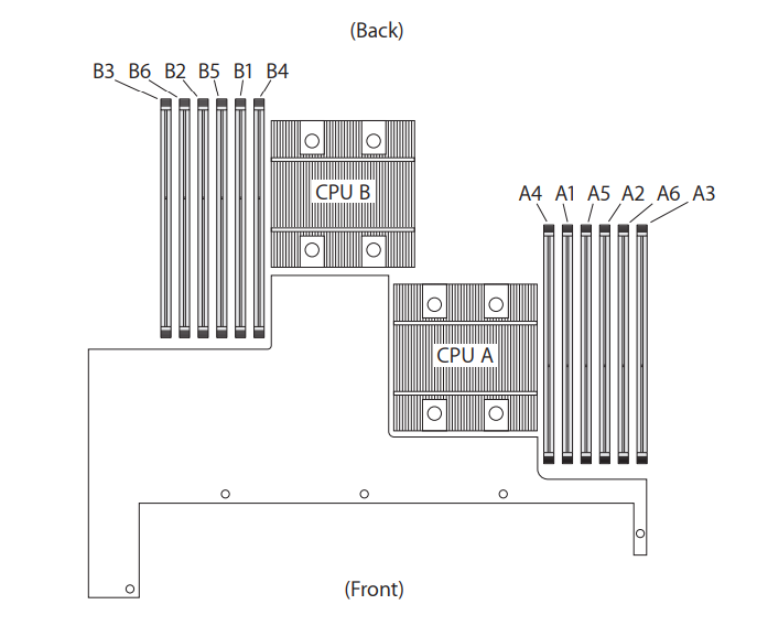
Installation Guidelines
For the best Xserve performance, install identical DIMMs as shown in the following table.
| Number of DIMMs | Install in these slots: | |
| 3 (single or dual CPU) | A1 A2 A3 | 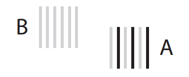 |
| 4 (dual CPU) | A1 A2 B1 B2 |
 |
| aa6 (single CPU) | A1 A2 A3 A4 A5 A6 |  |
| 6 (dual CPU | A1 A2 A3 B1 B2 B3 |
 |
| 8 (dual CPU) | A1 A2 A3 A4 B1 B2 B3 B4 |
|
| 10 (dual CPU) | A1 A2 A3 A4 A5 B1 B2 B3 B4 B5 |
 |
| 12 (dual CPU) | A1 A2 A3 A4 A5 A6 B1 B2 B3 B4 B5 B6 |
 |
For Best Performance
For the best possible performance from a dual-CPU Xserve, install six or twelve identical DIMMs in the slots shown in the table above. For a single-CPU Xserve, install three or six identical DIMMs. The Memory Slot Utility will advise you if your DIMM configuration can be improved. The utility runs automatically the first time you start up the Xserve after changing the memory configuration, or you can run it at any time from /System/ Library/CoreServices/Memory Slot Utility.
To install memory:
- Review the memory installation rules and make sure you have the right type of DIMMs.
- Shut down the Xserve and unplug all cables.
Important: Be sure the Xserve is turned off and the power cords are unplugged before you install or remove memory. - Remove the Xserve from the rack and open it. For instructions, see “Opening and Closing the Xserve” .
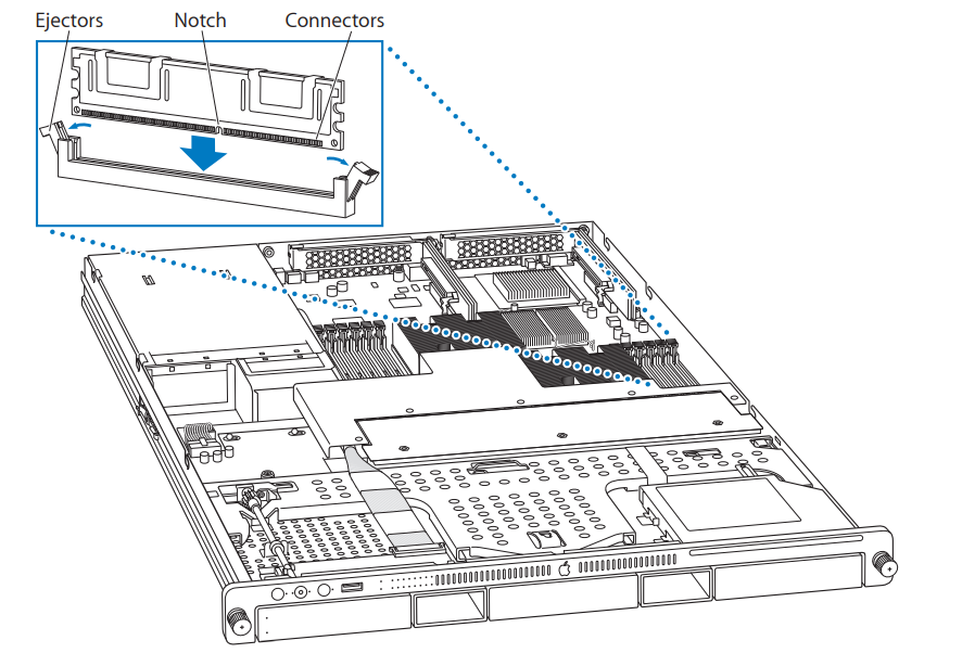
WARNING: Always wait 5 to 10 minutes for the Xserve to cool down before you try to install memory. DIMMs that are already installed and other components near the DIMM slots may be very hot. - Open the ejectors on a slot by pushing them outward.
Important: Don’t touch the gold connectors on the DIMMs. - Without touching its gold connectors, align a DIMM in the slot and push straight down on both ends until the DIMM is seated and the ejectors snap upright.
- Repeat for additional DIMMs.
- When you restart the Xserve, watch for the Memory Slot Utility’s evaluation of your new memory configuration.
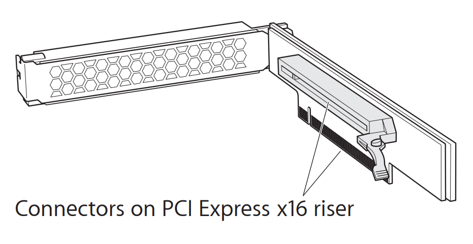
Installing a PCI Express Card
The Xserve has two PCI Express (PCI-E) slots:
- Slot 1 accepts 6.6 inch PCI-E cards
- Slot 2 accepts 9 inch PCI-E cards
To install a card, you first insert it into the included riser, and then insert the riser into the slot. Both slots accept the PCI-E riser shown below.
About PCI Express Cards for the Xserve
The Xserve accepts cards that meet these specifications:
- x16 PCI-E cards
- 6.6 inch maximum length (slot 1), 9 inch (slot 2)
- 25 W maximum power consumption per card
To install a PCI-E card:
- Shut down the Xserve and unplug all cables.
Important: Be sure the Xserve is turned off and the power cords are unplugged before you install or remove a PCI-E card or riser. - Remove the Xserve from the rack and open it. For instructions, see “Opening and Closing the Xserve” .
WARNING: Always wait 5 to 10 minutes for the Xserve to cool down before you work around the PCI-E slots. Components near the slots may be very hot.
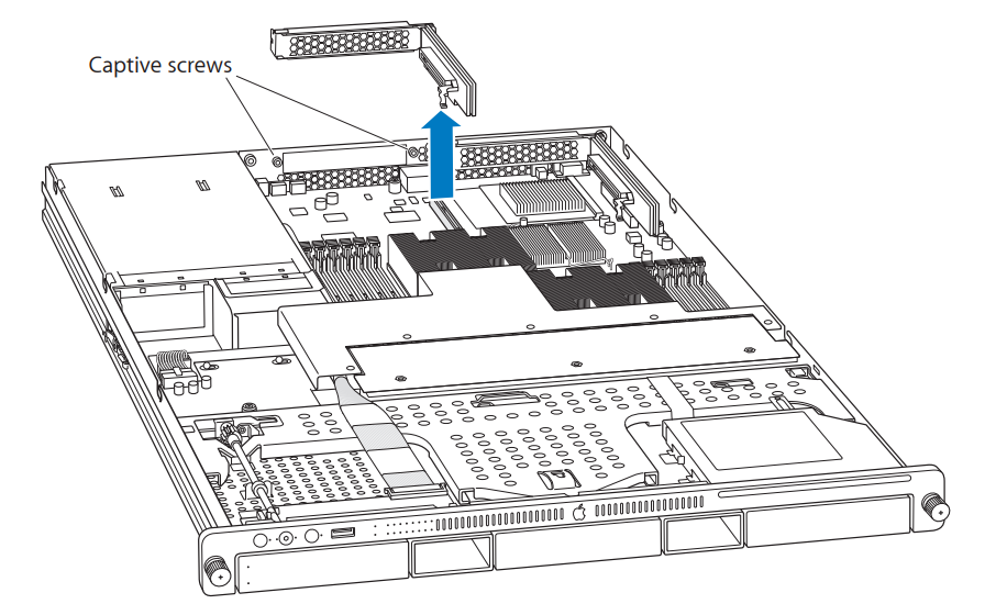
- Loosen the two captive screws that secure the riser bracket to the back panel and gently pull the bracket and riser straight up and out of the slot.
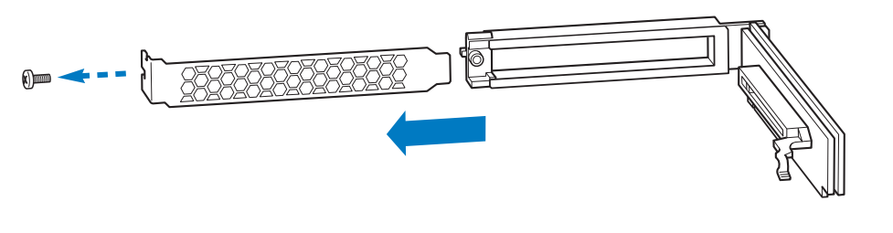
- Remove the screw on the riser bracket, and then remove the port access cover.
- Seat the card in the riser slot and replace the screw to secure the card in the riser.
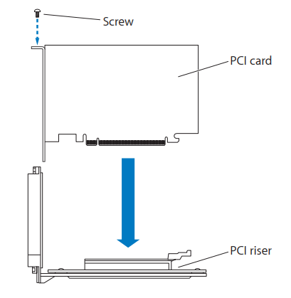
- Align the riser with the slot on the main logic board and press to seat it.
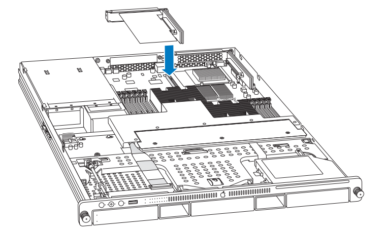
- Tighten the captive screws that secure the riser bracket to the back panel.
- Return the Xserve to the rack and start it up.
- Configure the card.
To configure an Ethernet card, open the Network pane of System Preferences.
To configure a Fibre Channel card, open Fibre Channel pane of System Preferences.
Replacing the Battery
The Xserve uses a BR 2032 lithium coin cell battery to preserve settings such as the date and time when the system is not connected to power. If the date and time change unexpectedly or other system settings are lost, you might need to replace the battery.
For best results, purchase a replacement battery from an Apple Authorized Service Provider.
To replace the battery:
- 1 Shut down the Xserve and unplug all cables.
Important: Be sure the Xserve is turned off and the power cords are unplugged before you replace the battery. - Remove the Xserve from the rack and open it. For instructions, see “Opening and Closing the Xserve”
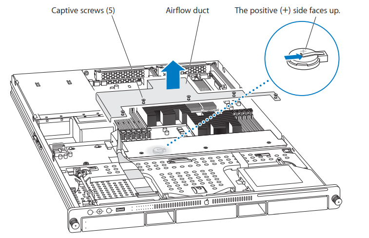
WARNING: Always wait 5 to 10 minutes for the Xserve to cool down before you try to replace the battery. Components near the battery may be very hot. - Loose the captive screws in the fan airflow duct and remove it.
- Remove the old battery from the holder.
WARNING: To avoid risk of explosion, replace the battery only with type BR 2032. - Insert the new battery in the holder with the positive (+) side facing up.
- Replace the fan airflow duct and tighten the screws gently.
- Close the Xserve and return it to the rack.
Important: Dispose of the old battery according to the manufacturer’s instructions and your local environmental laws. See the battery disposal information in the “Regulatory Compliance Information” section at the end of this guide.
Specifications
Dimensions
- Height: 1.73 in. (4.4 cm) (1U)
- Width: 17.6 in. (44.7 cm) for mounting in standard 19-in. rack
- Depth: 30 in. (76.2 cm)
Weight
- 32 lb. (14.5 kg) with 3 DIMMs, 1 drive module, and 1 power supply
- 39 lb. (17.5 kg) with 12 DIMMs, 3 drive modules, and 2 power supplies
Operating Environment
- Operating temperature: 50° to 95° F (10° to 35° C)
- Storage temperature: –40° to 116° F (–40° to 47° C)
- Relative humidity: 5% to 95% (noncondensing)
- Altitude: 0 to 10,000 feet (0 to 3048 meters)
Processors
- One or two 2.26, 2.66, or 2.93 gigahertz (GHz) Quad-Core Intel Xeon 5500 processors
- 8 megabytes (MB) shared L3 cache per processor
- Two Intel QuickPath Interconnect point-to-point links allowing up to 6.4
gigatransfers per second - Integrated memory controller with three independent DDR3-1066 memory channels per processor
Random-Access Memory
- 1066 MHz DDR3 ECC DIMMs (dual inline memory modules with address and data protection using error-correcting code)
- 12 DIMM slots accepting 1 GB, 2 GB, or 4 GB DIMMS
Optical Drive
- Slot-loading 24x (CD) / 8x (DVD) dual-layer SuperDrive
- Disc types supported: CD–R, CD–RW, DVD–R, DVD–R DL, DVD–RW, DVD+R, DVD+R DL, DVD+RW
- Disc dimensions supported: 12 cm (4.7 in.)
PCI-E Expansion Slot 1
- Accepts an x16 PCI-E (Express) card in a matching riser
- Maximum card length: 6.6 inches (16.7 cm)
- Maximum power consumption: 25 W
PCI-E Expansion Slot 2
- Accepts an x16 PCI-E card in a matching riser
- Maximum card length: 9 inches (22.8 cm)
- Maximum power consumption: 25 W
System Battery
- Long-life BR 2032 lithium coin cell battery
Ethernet
- IEEE 802.3 compliant
- Maximum cable length: 100 meters (m)
- Connectors: RJ-45 for 10Base-TX, 100Base-TX, and 1000Base-TX
- Media, 10Base-TX: Category 3 or higher UTP on 2 pairs up to 100 m
- Media, 100Base-TX: Category 5 UTP on 2 pairs up to 100 m
- Media, 1000Base-TX: Category 5 and 6 UTP on 4 pairs up to 100 m
- Channel speeds: IEEE Auto Negotiation of 10Base-TX, 100Base-TX, and 1000Base-TX
FireWire
- Data transfer speed: 100, 200, up to 400, and up to 800 megabits per second
- Two FireWire 800 ports (back panel)
With an appropriate cable, the FireWire 800 ports work with all FireWire devices.
Cables are available for connecting a 9-pin port to a 4-pin, 6-pin, or 9-pin device. - Output voltage range: Approximately 12 to 30 V
- Output power range: Up to 15 W
USB
- Support for USB 2.0
- Three external Universal Serial Bus (USB) Type A ports
- Separate 480 megabit per second (Mbit/s) USB channel for each port
- 500 milliamperes (mA) at 5 V available per port for a total of 2.5 ampere (A)
- Any one port can supply 1.5 W (the other two ports then supply 500 mW)
Power Supply
- One or two 750 W power supplies
- AC line input: 100–240 V alternating current (AC), single phase, 50–60 hertz (Hz)
- Maximum AC line current: 9.5 A (100–127 V) or 5 A (200–240 V). If two power supplies are installed, they split this load.
Serial Port
- 9-pin D connector
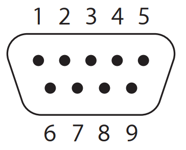
- Pin signals
- Received line signal detector (RLSD)
- Received data (RD)
- Transmitted data (TD)
- DTE ready (DRT CD)
- Signal ground (SGND)
- DCE ready (DCR CC)
- Request to send (RTS)
- Clear to send (CTS)
- Ring indicator (RI)
Safety and Maintenance
Important Safety Information
For your own safety and that of your equipment, always take the following precautions.
Important: The only way to shut off power completely is to unplug the power cord.
Make sure at least one end of the power cord is within easy reach, so you can unplug the Xserve when you need to.
Disconnect the power plug (by pulling the plug, not the cord) if any of the following conditions exist:
- You want to remove any parts (leave the cord disconnected as long as the cover is off).
- The power cord or plug becomes frayed or otherwise damaged.
- You spill something into the case.
- The Xserve is exposed to rain or any other excessive moisture.
- The Xserve has been dropped or the case has been otherwise damaged.
- You suspect that the Xserve needs service or repair.
- You want to clean the case (use only the recommended procedure described later).
Be sure that you always do the following:
- Keep the Xserve away from sources of liquid, such as washbasins, bathtubs, shower stalls, and so on.
- Protect the Xserve from dampness or wet weather, such as rain and snow.
- Read all the installation instructions carefully before you plug the Xserve into a grounded electrical outlet or power strip.
- Keep these instructions handy for reference by you and others.
- Follow all instructions and warnings dealing with the Xserve.
Electrical equipment may be hazardous if misused.
The model of server described in this manual is certified only as a component for use with other equipment, where the suitability of the combination has been determined by a Nationally Recognized Testing Laboratory.
Handling the Xserve
Follow these guidelines for handling the Xserve and its components:
- When the Xserve is removed from the rack, set it on a sturdy, flat surface.
Important: Do not put a display or any other device on top of the Xserve. Any weight on top of the case could damage essential components inside the Xserve. - When connecting or disconnecting a cable, always hold the cable by its connector (the plug, not the cord).
- Certain components and cables—hard disks, a VGA monitor, FireWire, Ethernet, and USB devices—are designed to be installed or removed while the Xserve is turned on and operating.
- Never force a connector into a port. If the connector and port do not join with reasonable ease, they probably don’t match. Make sure that the connector matches the port and that you have positioned the connector correctly in relation to the port.
- Take care not to spill any food or liquid on the Xserve or other components. If you do, turn off the Xserve immediately and unplug it before cleaning up the spill.
Arrange for an Apple Authorized Service Provider to inspect or repair the Xserve. - Protect the Xserve and its components from direct sunlight and rain or other moisture.
- Keep all ventilation openings clear and unobstructed. Without proper air circulation, components can overheat, causing damage or unreliable operation.
Protecting the Optical Drive
To keep the optical drive working properly:
- In an emergency, you can eject a disc by holding down the mouse button as the system starts up. If no mouse is attached, you can eject the disc by using the front panel controls to start up from the optical drive. For instructions, see the Xserve User Guide on the Admin Tools disc that comes with the Xserve.
Whenever possible, eject the disc before shutting down.
Power Supply
The power supply in the Xserve is a high-voltage component that should not be opened for any reason, even when the computer is off. If the power supply needs service, contact an Apple Authorized Service Provider.
Cleaning the Xserve
Follow these recommendations when cleaning the outside of the Xserve:
- Use a damp, soft, lint-free cloth to clean the exterior. Avoid getting moisture in any openings.
- Don’t use aerosol sprays, solvents, or abrasives
Cleaning the Xserve Case
To clean the case:
- Turn off the computer completely and then disconnect the power plug (pull the plug, not the cord).
- Wipe the surfaces lightly with a clean, soft cloth dampened with water.
Apple and the Environment
Apple recognizes its responsibility to minimize the environmental impacts of its operations and products. For more information, go to www.apple.com/environment.
Health-Related Information About Computer Use
In most instances, you’ll probably set up and administer the Xserve from a remote location, such as an administrator computer on the same network. If you work at the server rack for extended periods, be sure to follow these guidelines for avoiding muscle soreness, eye fatigue, or other discomfort associated with computer use:
- If feasible in the server location, use an adjustable chair that provides firm, comfortable support. The back of the chair should support your lower back (lumbar region). Follow the manufacturer’s instructions for adjusting the backrest to fit your body properly.
- When using a keyboard at the server location, your shoulders should be relaxed. Your upper arm and forearm should form an approximate right angle, with your wrist and hand roughly in a straight line. Depending on the location of the display and keyboard connected to the Xserve, you may have to adjust the height of your chair so that you can maintain a comfortable position. Your feet should be flat on the floor or on a footrest.
Regulatory Compliance Information
FCC Compliance Statement
This equipment has been tested and found to comply with the limits for a class A digital device pursuant to Part 15 of the FCC Rules. These limits are designed to provide reasonable protection against harmful interference when the equipment is operated in a commercial environment. This equipment generates, uses, and can radiate radio frequency energy and, if not installed and used in accordance with the manufacturer’s instruction manual, may cause harmful interference with radio communications. Operation of this equipment in a residential area is likely to cause harmful interference, in which case you will be required to correct the interference at your own expense.
Shielded Cable Statement & Modification Statement
This product was tested for EMC compliance under conditions that included the use of Apple peripheral devices and Apple shielded cables and connectors between system components. It is important that you use Apple peripheral devices and shielded cables and connectors between system components to reduce the possibility of causing interference to radios, television sets, and other electronic devices. You can obtain Apple peripheral devices and the proper shielded cables and connectors through an Apple-authorized dealer. For non-Apple peripheral devices, contact the manufacturer or dealer for assistance.
Important: Changes or modifications to this product not authorized by Apple Inc. could void the EMC compliance and negate your authority to operate the product.
Industry Canada Statement
Complies with the Canadian ICES-003 Class A specifications. Cet appareil numérique de la classe A est conforme à la norme NMB-003 du Canada.
Statement for Norway
Dette utstyret har blitt evaluert og er egnet for bruk på et IT-Power-system.
Statement for Germany
Das Produkt ist nicht für den Einsatz an Bildschirmarbeitsplätzen im Sinne § 2 der Bildschirmarbeitsplatzverordnung geeignet.
Die arbeitsplatzbezogene Geräuschemission des Gerätes beträgt <70 dB(A).
VCCI Class A Statement
Europe-EU Declaration of Conformity
See www.apple.com/euro/compliance
CISPR 22 & EN55022 Statement
WARNING: This is a Class A product. In a domestic environment this product may cause radio interference, in which case the user may be required to take adequate measures.
Taiwan Class A Warning
Korea Class A Warning
China Class A Warning
Laser Information
WARNING: Making adjustments or performing procedures other than those specified in your equipment’s manual may result in hazardous radiation exposure.
Do not attempt to disassemble the cabinet containing the laser. The laser beam used in this product is harmful to the eyes. The use of optical instruments, such as magnifying lenses, with this product increases the potential hazard to your eyes. For your safety, have this equipment serviced only by an Apple Authorized Service Provider.
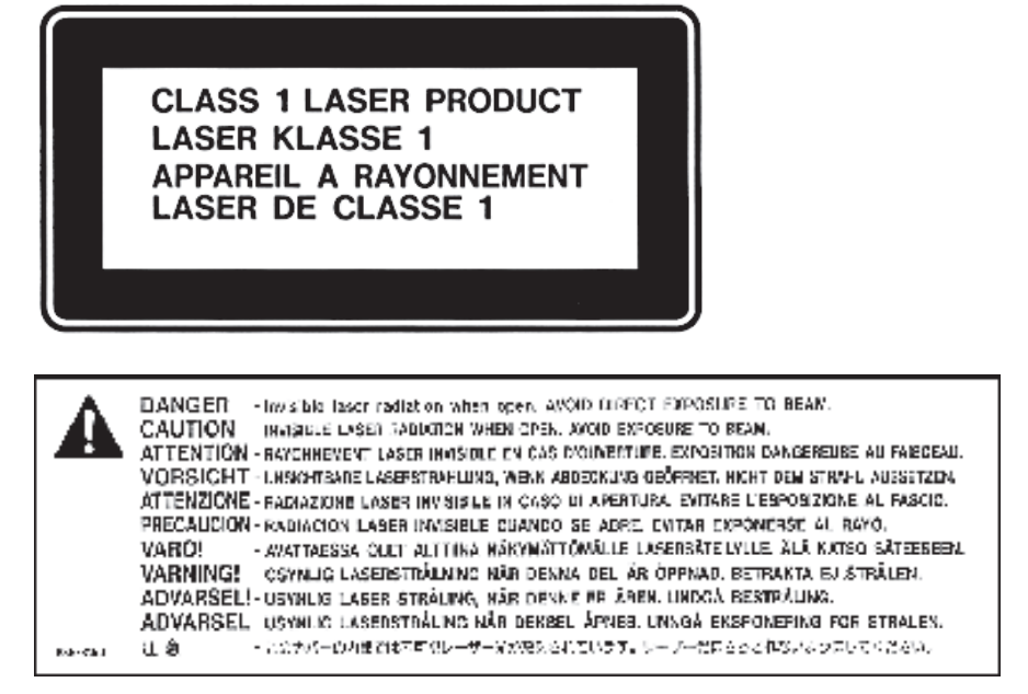
If you have an internal Apple CD-ROM, DVD-ROM, or DVD-RAM drive in your computer, your computer is a Class 1 laser product. The Class 1 label, located in a useraccessible area, indicates that the drive meets minimumsafety requirements. A service warning label is located in a service-accessible area. The labels on your product may differ slightly from the ones shown here.
High-Risk Activities Warning
This computer system is not intended for use in the operation of nuclear facilities, aircraft navigation or communications systems, or air traffic control machines, or for any other uses where the failure of the computer system could lead to death, personal injury or severe environmental damage.
Disposal and Recycling Information
This symbol indicates that your product must be disposed of properly according to local laws and regulations. When your product reaches its end of life, contact Apple or your local authorities to learn about recycling options.
For information about Apple’s recycling program, go to www.apple.com/environment/recycling.
Battery Disposal Information
![]() When replacing the internal battery, dispose of the spent battery according to your local environmental laws and guidelines.
When replacing the internal battery, dispose of the spent battery according to your local environmental laws and guidelines.
Nederlands: Gebruikte batterijen kunnen worden ingeleverd bij de chemokar of in een speciale batterijcontainer voor klein chemisch afval (kca) worden gedeponeerd.
![]() Deutschland: Das Gerät enthält Batterien. Diese gehören nicht in den Hausmüll. Sie können verbrauchte Batterien beim Handel oder bei den Kommunen unentgeltlichabgeben.Um Kurzschlüsse zu vermeiden, kleben Sie die Pole der Batterien vorsorglich mit einem Klebestreifen ab.
Deutschland: Das Gerät enthält Batterien. Diese gehören nicht in den Hausmüll. Sie können verbrauchte Batterien beim Handel oder bei den Kommunen unentgeltlichabgeben.Um Kurzschlüsse zu vermeiden, kleben Sie die Pole der Batterien vorsorglich mit einem Klebestreifen ab.
![]() Taiwan
Taiwan
European Union—Disposal Information:
The symbol above means that according to local laws and regulations your product should be disposed of separately from household waste. When this product reaches its end of life, take it to a collection point designated by local authorities. Some collection points accept products for free. The separate collection and recycling of your product at the time of disposal will help conserve natural resources and ensure that it is recycled in a manner that protects human health and the environment
Union Européenne: informations sur l’élimination
Le symbole ci-dessus signifie que vous devez vous débarasser de votre produit sans le mélanger avec les ordures ménagères, selon les normes et la législation de votre pays. Lorsque ce produit n’est plus utilisable, portezle dans un centre de traitement des déchets agréé par les autorités locales. Certains centres acceptent les produits gratuitement. Le traitement et le recyclage séparé de votre produit lors de son élimination aideront à préserver les ressources naturelles et à protéger l’environnement et la santé des êtres humains.
![]() Europäische Union – Informationen zur Entsorgung
Europäische Union – Informationen zur Entsorgung
Das Symbol oben bedeutet, dass dieses Produkt entsprechend den geltenden gesetzlichen Vorschriften und getrennt vom Hausmüll entsorgt werden muss. Geben Sie dieses Produkt zur Entsorgung bei einer offiziellen Sammelstelle ab. Bei einigen Sammelstellen können Produkte zur Entsorgung unentgeltlich abgegeben werden. Durch das separate Sammeln und Recycling werden die natürlichen Ressourcen geschont und es ist sichergestellt, dass beim Recycling des Produkts alle Bestimmungen zum Schutz von Gesundheit und Umwelt beachtet werden.
Unione Europea: informazioni per lo smaltimento
Il simbolo qui sopra significa che, in base alle leggi e alle norme locali, il prodotto dovrebbe essere smaltito separatamente dai rifi uti casalinghi. Quando il prodotto diventa inutilizzabile, portalo nel punto di raccolta stabilito dalle autorità locali. Alcuni punti di raccolta accettano i prodotti gratuitamente. La raccolta separata e il riciclaggio del prodotto al momento dello smaltimento aiutano a conservare le risorse naturali e assicurano che venga riciclato nel rispetto della salute umana e dell’ambiente.
Europeiska unionen – uttjänta produkter
Symbolen ovan betyder att produkten enligt lokala lagar och bestämmelser inte får kastas tillsammans med hushållsavfallet. När produkten har tjänat ut måste den tas till en återvinningsstation som utsetts av lokala myndigheter. Vissa återvinningsstationer tar kostnadsfritt hand om uttjänta produkter. Genom attlåta den uttjänta produkten tas om hand för återvinning hjälper du till att spara naturresurser och skydda hälsa och miljö.
![]() Apple Inc.
Apple Inc.
© 2009 Apple Inc. All rights reserved.
Under the copyright laws, this manual may not be copied, in whole or in part, without the written consent of Apple. Your rights to the software are governed by the accompanying software license agreement.
The Apple logo is a trademark of Apple Inc., registered in the U.S. and other countries. Use of the “keyboard” Apple logo (Option-Shift-K) for commercial purposes without the prior written consent of Apple may constitute trademark infringement and unfair competition in violation of federal and state laws.
Every effort has been made to ensure that the information in this manual is accurate. Apple is not responsible for printing or clerical errors.
Apple
1 Infinite Loop
Cupertino, CA 95014-2084
408-996-1010
www.apple.com
Apple, the Apple logo, FireWire, Mac, Mac OS, Macintosh, Macintosh Products Guide, SuperDrive, and Xserve are trademarks of Apple Inc., registered in the U.S. and other countries.
Apple Remote Desktop and the FireWire logo are trademarks of Apple Inc.
Apple Store is a service mark of Apple Inc., registered in the U.S. and other countries.
Intel, Intel Core, and Xeon are trademarks of Intel Corp. in the U.S. and other countries.
This product includes software developed by the University of California, Berkeley, FreeBSD, Inc., The NetBSD Foundation, Inc., and their respective contributors.
Other company and product names mentioned herein may be trademarks of their respective companies.
Mention of third-party products is for informational purposes only and constitutes neither an endorsement nor a recommendation. Apple assumes no responsibility with regard to the performance or use of these products.
Simultaneously published in the United States and Canada.
034-4891-A/2009-02

PDF Resource
Apple Xserve Setup Guide Setup and Hardware Specifications User Manual OPTIM PDF