Apple Xserve Early 2008 Drive Interconnect Backplane Replacement
Drive Interconnect Backplane Replacement Instructions
Follow the instructions in this document carefully. Failure to follow these instructions could damage your equipment and void its warranty.
Online instructions are available at http://www.apple.com/support/diy/.
Working Safely Inside the Xserve
Always touch the Xserve enclosure to discharge static electricity before you touch any components inside the Xserve. To avoid generating static electricity, do not walk around the room until you have finished working inside the server and have replaced the cover. To minimize the possibility of damage due to static discharge, wear an antistatic wrist strap while you work inside the Xserve.
Warning: Always shut down the Xserve and disconnect the power cords before opening it to avoid damaging its internal components or the components you are installing. Don’t open the server while it is turned on. Even after you shut down the Xserve, its internal components can be very hot. Let it cool before you open it.
Tools Required
The only tool required for this procedure is a Phillips #1 screwdriver. You may also find a small flatblade screwdriver useful in releasing the connectors on the power distribution board cable.
Removing the Xserve from a Rack
- Alert users that the server will be unavailable for a period of time.
- Shut down the Xserve (see the Xserve User’s Guide for help) and then wait to let the Xserve internal components cool.
Warning: Always shut down the Xserve before opening it to avoid damaging its internal components or the components you want to install or remove. Don’t open the Xserve or try to install or remove items inside while it is turned on. Even after you shut down the Xserve, its internal components can be very hot. Let it cool down for 5 to 10 minutes before you open it. - Unplug all cables from the Xserve.
Note: If you have trouble releasing a cable from the back panel, try using a small screwdriver or other flat tool to depress the tab on the cable connector. - To avoid inadvertently unlatching a drive module during handling, use the enclosure key to lock the enclosure lock on the front panel.
- Touch the server’s metal case to discharge any static electricity.
- Loosen the thumbscrews at both ends of the front panel.
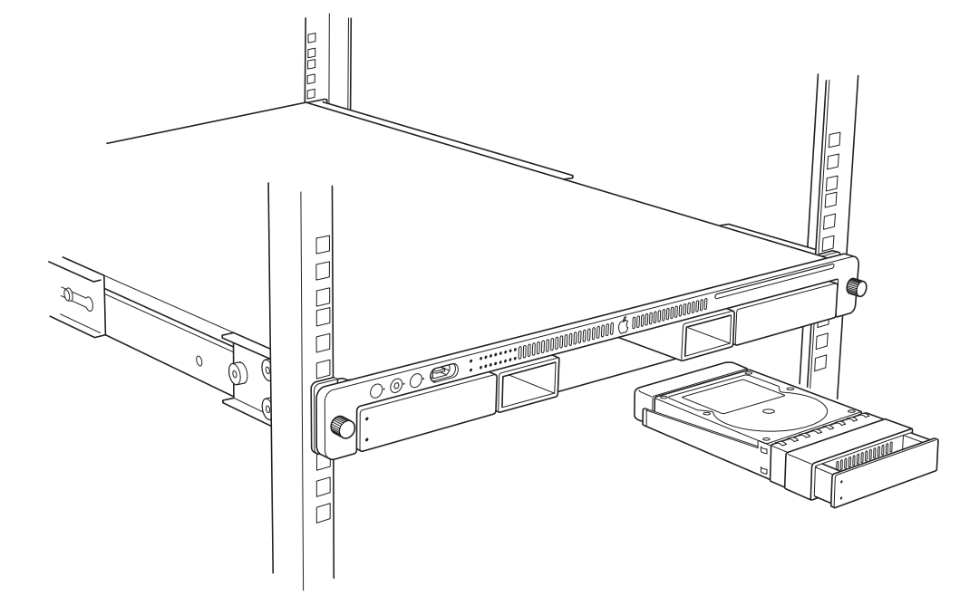
- Grasp the thumbscrews and pull the Xserve forward until the safety latches engage (about halfway out of the rack).
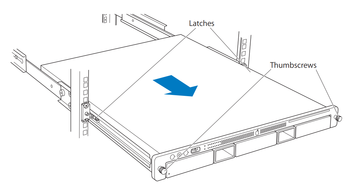
- When the safety latches engage, grip the Xserve where it emerges from the rack, press down on the latch tabs with your thumbs, and slide the Xserve the restof the way out of the rack.
- Set the Xserve on a flat surface and unlock it.
Opening the Xserve
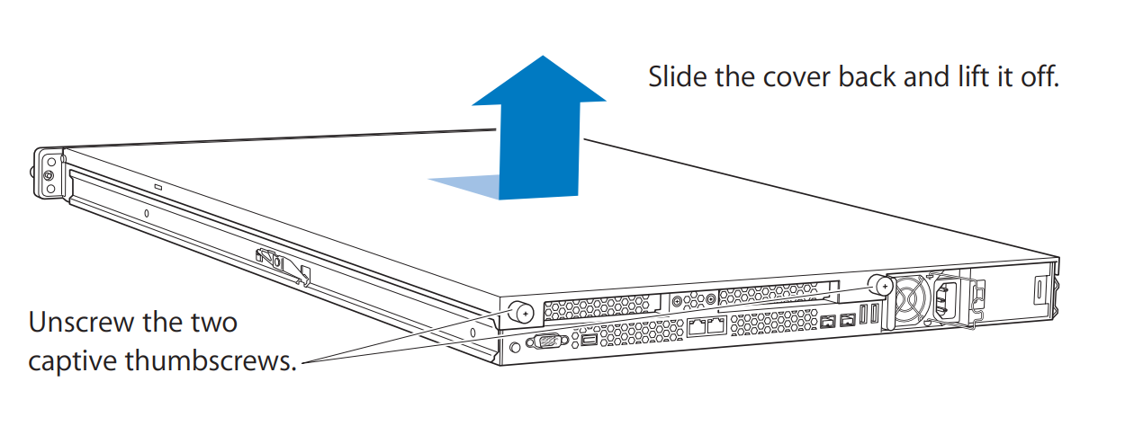
Loosen the thumbscrews at the back of the top cover and slide the cover back and up to remove it. If you have difficulty removing the cover, check the enclosure lock on the front panel.
Warning: Even after you shut down the Xserve, its internal components can be very hot. Let it cool before you open it.
Important: To minimize the possibility of damage to Xserve components due to static discharge, wear an antistatic wrist strap, if possible, while you work inside the Xserve.
Removing the Installed Drive Interconnect Backplane
Note: Before removing the power distribution board, you must remove the following:
- All Apple drive modules
- Airflow duct
- Fan array
Apple Drive Modules
- Press the handle on the front of the drive module so that the handle pops out. Then grasp the drive handle, and pull the drive module out of the Xserve.
- Repeat for all other installed drive modules.
Airflow Duct
- Loosen the five Phillips screws that fasten the airflow duct to the fan array.
- Pull up on either side of the airflow duct, and lift it straight up and out of the Xserve.
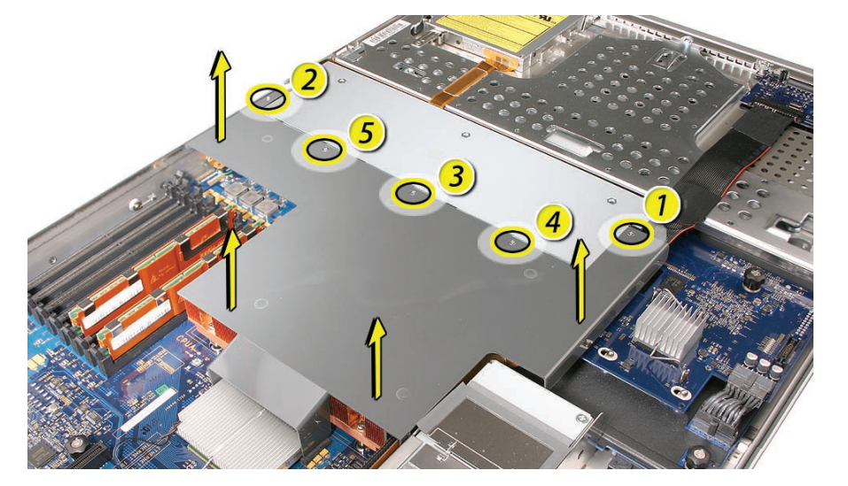
Caution: Try not to completely remove the screws from the airflow duct. Tiny black rubber washers hold these screws captive on the underside of the airflow duct. If the screws are completely removed, these washers can easily fall into the enclosure and become lost.
Fan Array
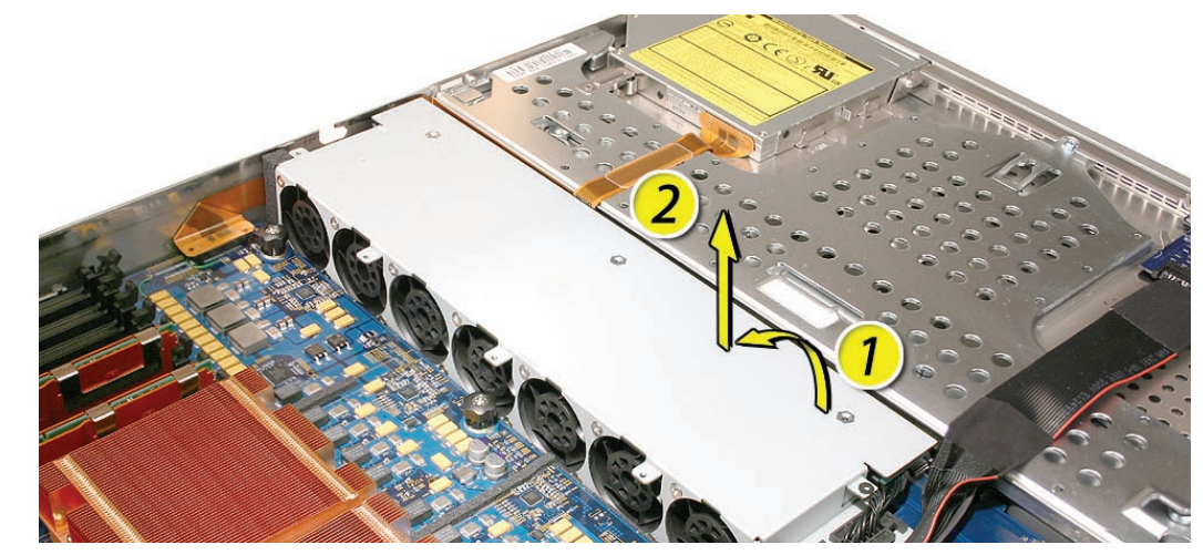
- Loosen the two thumbscrews that secure the fan array to the enclosure.
Note: The thumbscrews are captive; you cannot remove them. - Lift the fan array to remove it from the Xserve.
Note: You may need to move the front panel cable slightly out of the way of the fan array power connector during removal or replacement. Be careful not to pinch the front panel board cable between the fan array and any other surface inside.
Note: You may encounter some resistance around the fan array power connector during removal.
If so, carefully rotate the fan array as shown to disconnect it from the power distribution board below, and then lift the fan array out of the computer.
Drive Interconnect Backplane
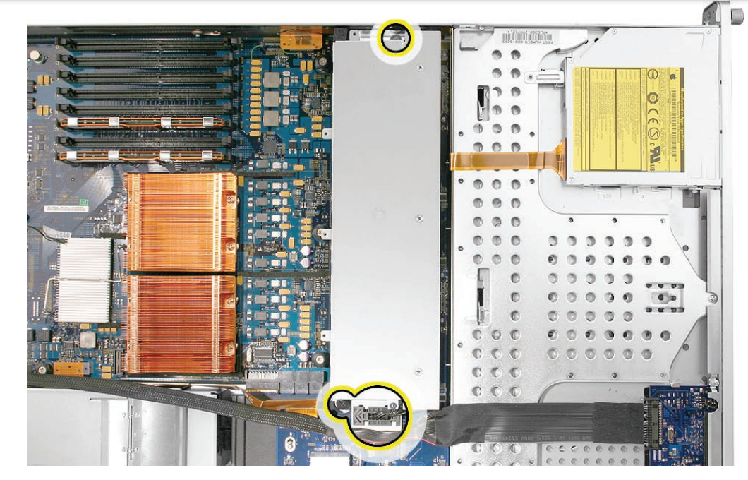
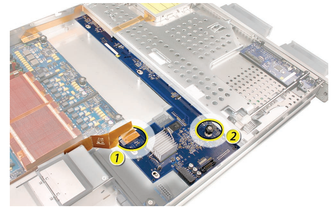
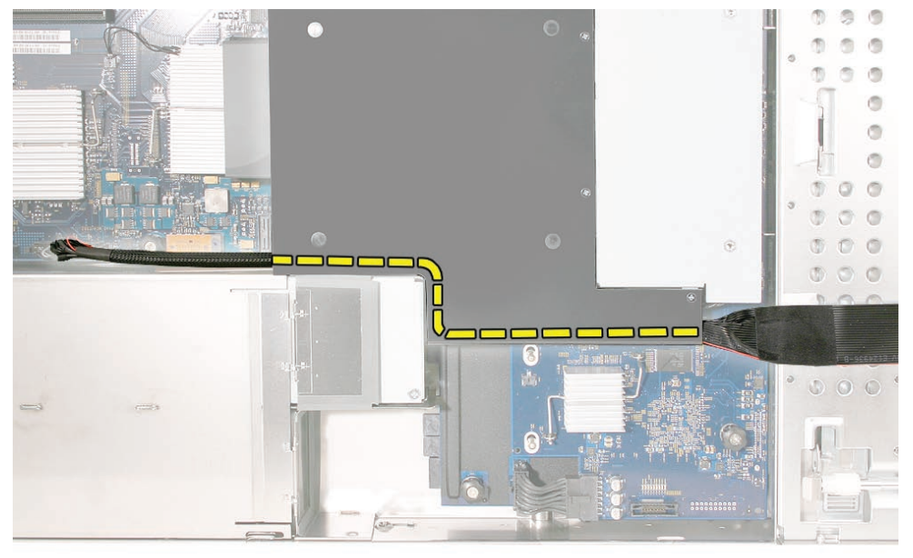
- Locate the power distribution board cable.
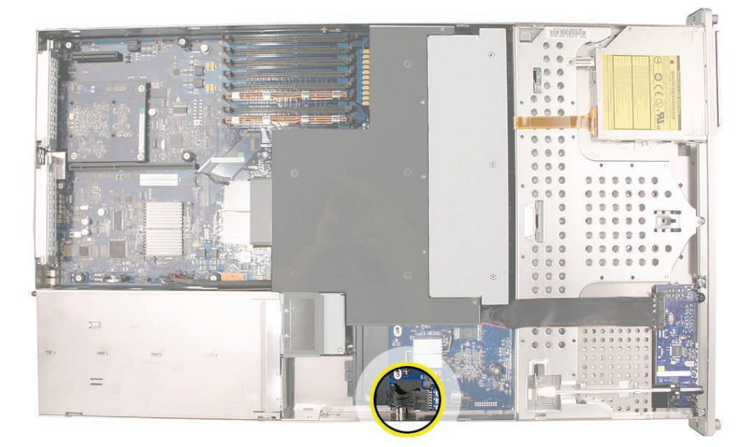
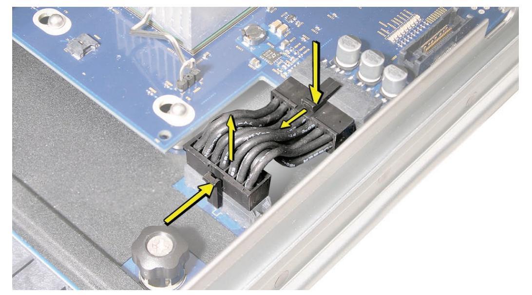
- Disconnect the power distribution board cable from the drive interconnect backplane and the power distribution board. Remove the cable from the enclosure.
Caution: The power distribution board cable connectors are very tight and can be difficult to disconnect. You may want to use a small flatblade screwdriver to gently yet firmly pry outwards on the cable connector while depressing the cable connector latch with your thumb and forefinger to separate the connectors.
- Release the two locking levers on the front panel board cable connector and disconnect the cable from the front panel board. Move the front panel board cable out of the way.
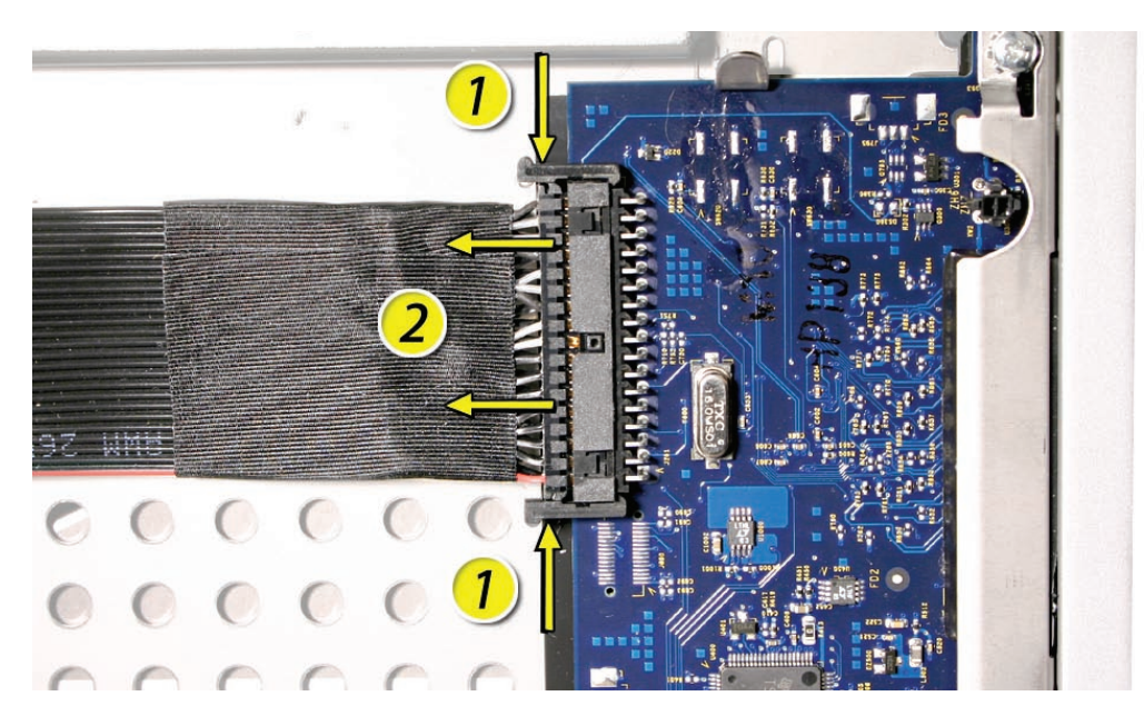
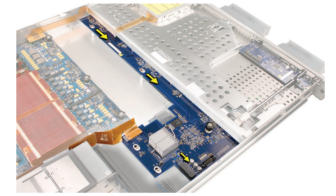
- Disconnect the backplane-to-logic board I/O cable from the backplane.
- Loosen the thumbscrew that secures the backplane to the enclosure.
Note: The thumbscrew is captive; you cannot remove it.
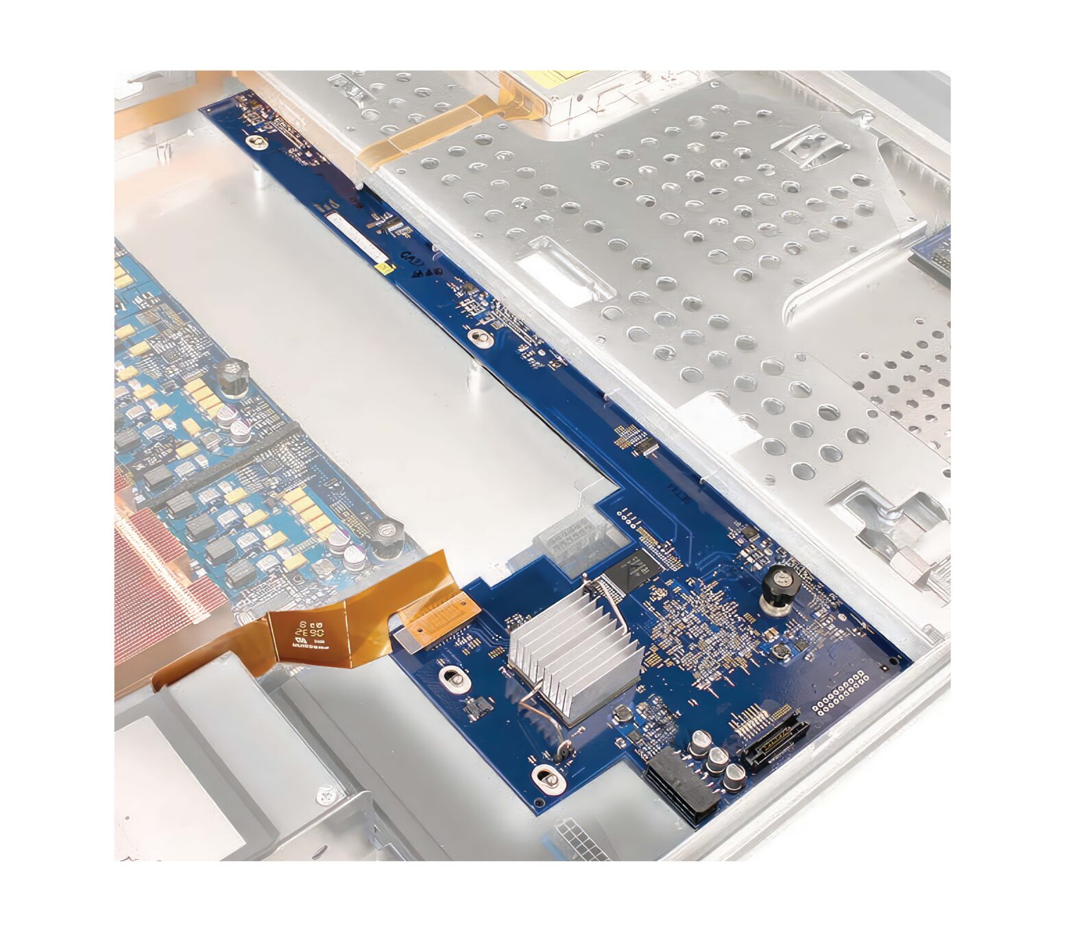
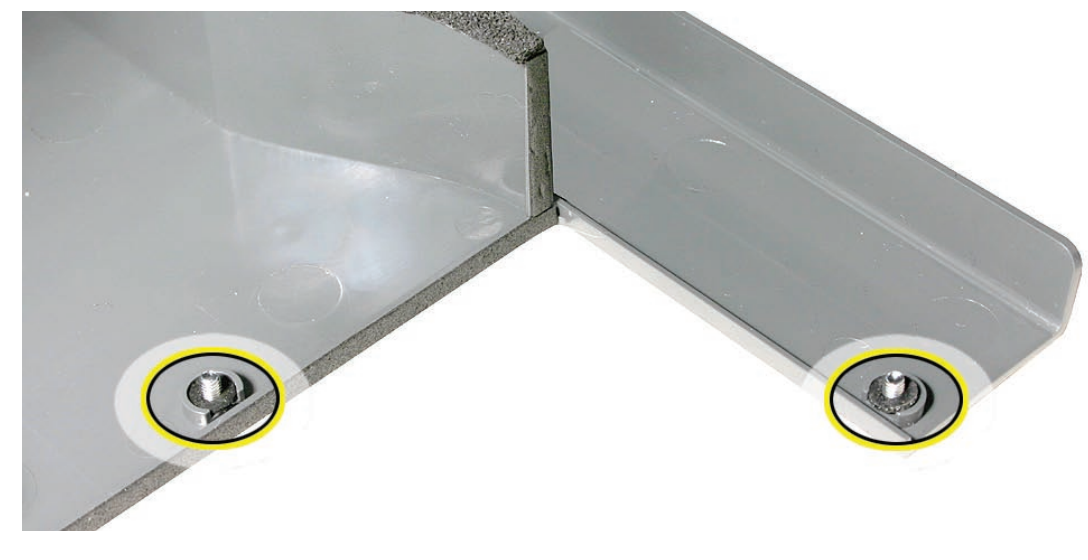
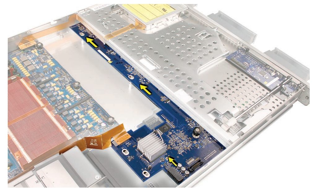
- Shift the backplane to the left (towards the enclosure side), in the direction of the arrow shown, until it clears the four mushroom-shaped standoffs that hold the backplane in place.
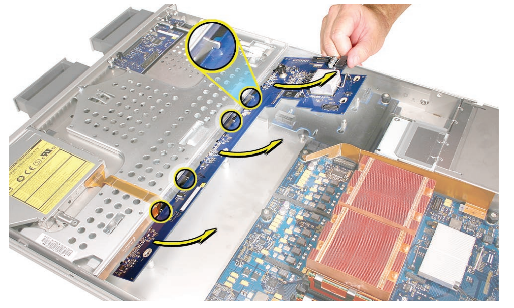
- Rotate the backplane up slightly from the logic board side (as shown), and carefully pull the backplane up and toward the logic board to free it from the standoffs and four backplane alignment slots in the enclosure. Be careful not to let any backplane components come into contact with the standoffs or the enclosure as you remove the backplane.
Installing the Replacement Drive Interconnect Backplane
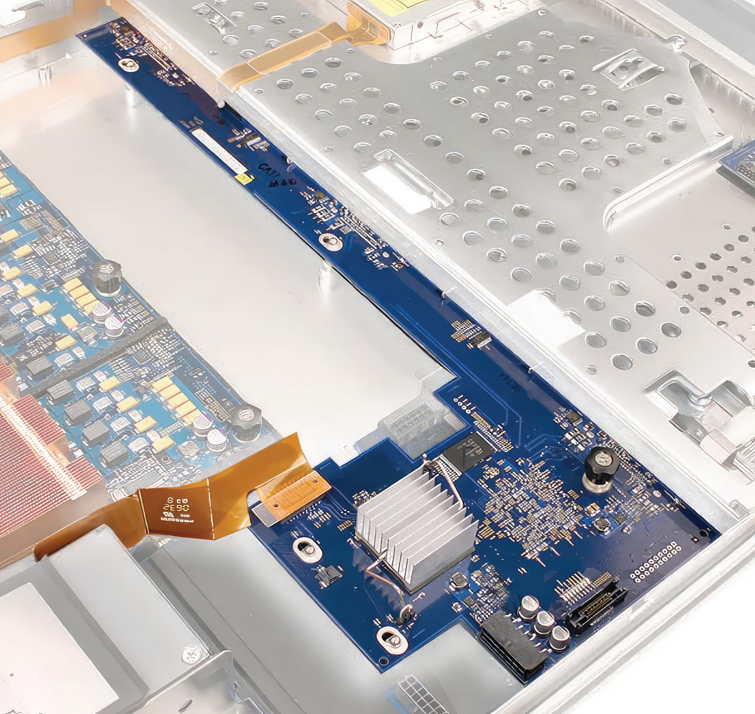
- Lower the replacement backplane into the enclosure at a slight angle (as shown), and carefully align the front edge of the backplane with the four backplane alignment slots in the enclosure. Be careful not to let any backplane components come into contact with the standoffs or the enclosure as you install the backplane.
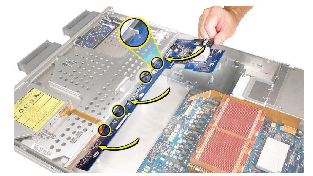
- Rotate the backplane downward and over the four mushroom-shaped standoffs.
- Slide the backplane in the direction of the arrow shown to fully seat the backplane in the enclosure.
- Tighten the thumbscrew that secures the backplane to the enclosure.
- Reconnect the backplane-to-logic board I/O cable to the backplane. Caution: Make sure the cable is completely seated.
- Reconnect the front panel board cable to the front panel board.
- Reconnect the power distribution board cable to the backplane and power distribution board.
Replacing the Fan Array
- Align the power connector on the fan array with its connector on the power distribution board and lower the array into the enclosure. Push down on the fan array power connector to make sure it is fully seated.
- Tighten the screws at the ends of the array. Make sure the large front panel board cable runs above the power connector but below the tab on the top of the power supply
Replacing the Airflow Duct
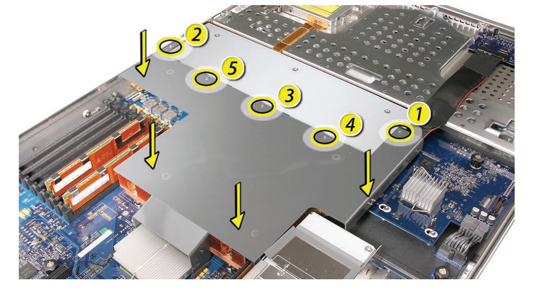
- Lower the airflow duct into position on the logic board.
Note: When installing the airflow duct, be sure to route both the front panel board cable and the backplane-to-logic board I/O cable inside the channel under the left side of the duct.
- Ensure the airflow duct fits flush all over, and does not protrude above the level of the enclosure.
Note: Be careful when working with any black foam pieces that are part of the airflow duct or the logic board. - Tighten the five Phillips screws that fasten the airflow duct to the fan array, in the order shown, to prevent the duct from warping. Do not overtighten the screws.
Replacing the Apple Drive Modules
- Slide the first Apple drive module into its bay until it is firmly seated. Then press the handle in flush with the front panel.
- Repeat for all other installed drive modules.
Closing the Xserve
- Replace and secure the cover.
- Slide the Xserve back into the rack, and tighten the front thumbscrews to secure the Xserve in the rack.
- If the server case was locked, use the enclosure key to lock the security lock on the front panel.
Warning: Never turn on the server unless all of its internal and external parts are in place and it is closed. Operating the server when it is open or missing parts can damage it or cause injury.
![]() Apple Inc.
Apple Inc.
© 2006, 2008 Apple Inc. All rights reserved.
Under the copyright laws, this document may not be copied, in whole or in part, without the written consent of Apple.
Every effort has been made to ensure that the information in this document is accurate. Apple is not responsible for printing or clerical errors.
Apple
1 Infinite Loop
Cupertino, CA 95014-2084
USA
+ 1 408 996 1010
http://www.apple.com
Apple, the Apple logo, Mac, Macintosh, and Xserve are trademarks of Apple Inc., registered in the U.S. and other countries.

PDF Resource
Apple Xserve Early 2008 Drive Interconnect Backplane Replacement Instructions Manual OPTIM PDF